
Brochure
To learn more about GS Fire Safety products, you can download documents here

Customer Support!
Contact:
P. +(84) 251 3685 600
E. help@gsfiresafety.com
Nhon Trach III - Phase 2 IZ
Nhon Trach, Dong Nai
G-Flex Speciality A1
Description
Description
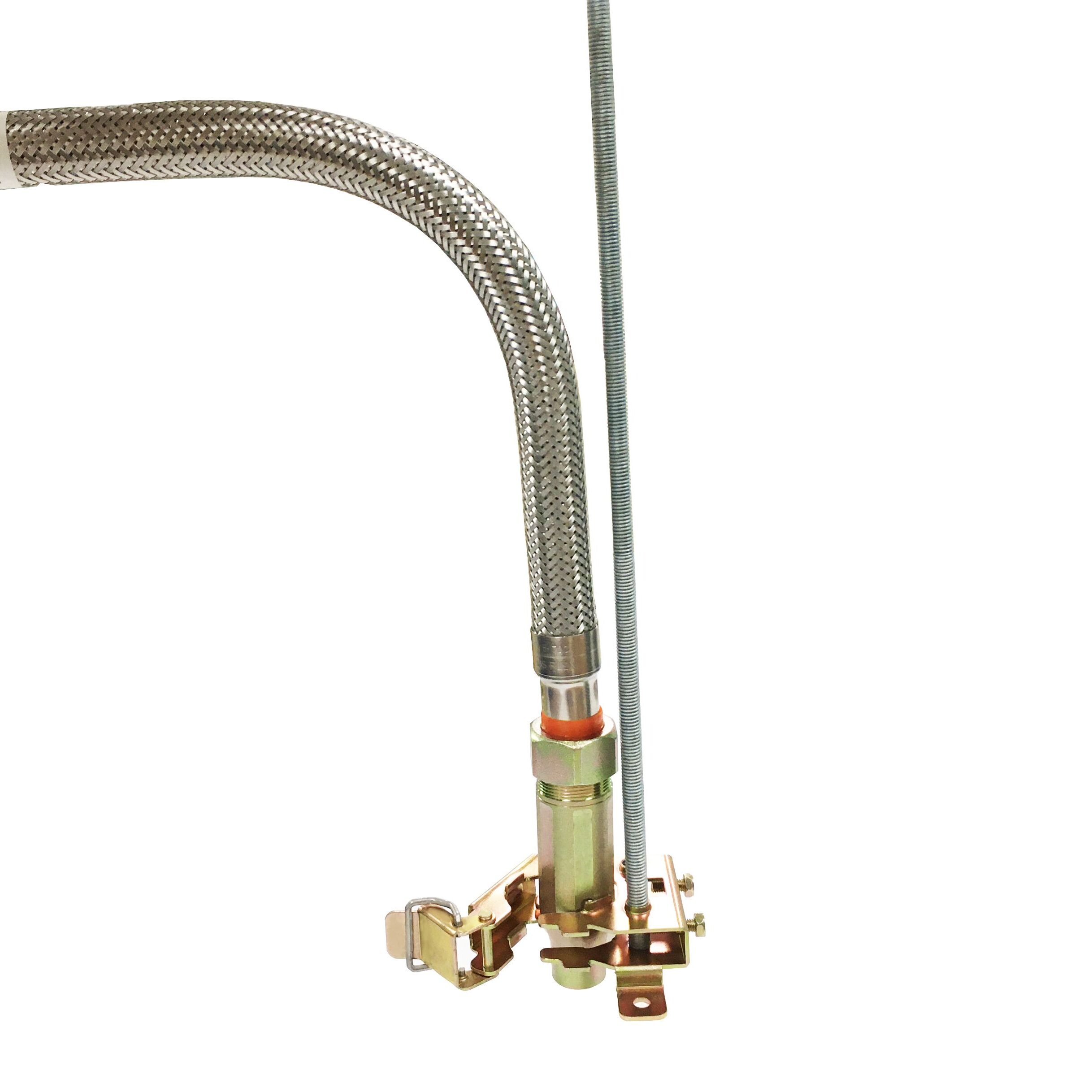
The Specialty A1 solution is simply designed with a middle bracket combined with a common hanging rod, the special structure of the bracket helps to hold the sprinkler head strongly. With a convenient hand-lock, disassembly becomes extremely easy with just one operation, without the need for any additional tools such as screwdrivers or wrenches.
Firmly anchored to a concrete ceiling with a rod, the center brackets hold tightly a sprinkler head, the Specialty A1 is not only a solution reserved for drywall ceilings but also an effective alternative to any non ceiling project.
Components
Components of SPECIALTY A1 including:
- Stainless steel hose
- Nut
- Nipple
- Reducer
- Center bracket

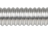
1. Stainless steel hose

2. Nut

3. Nipple
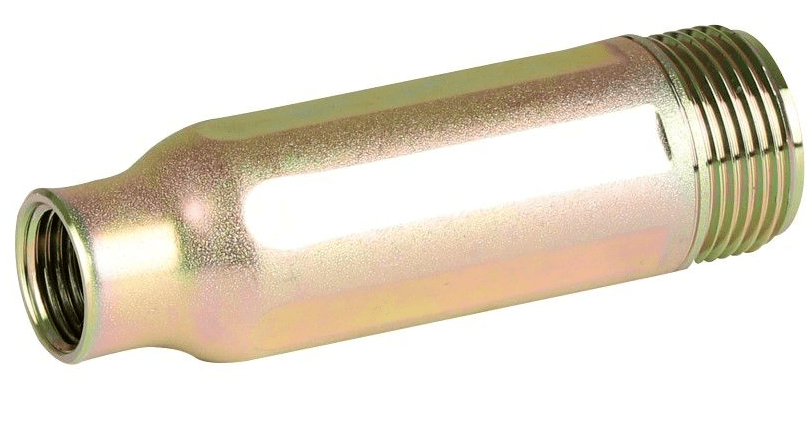
3. Reducer
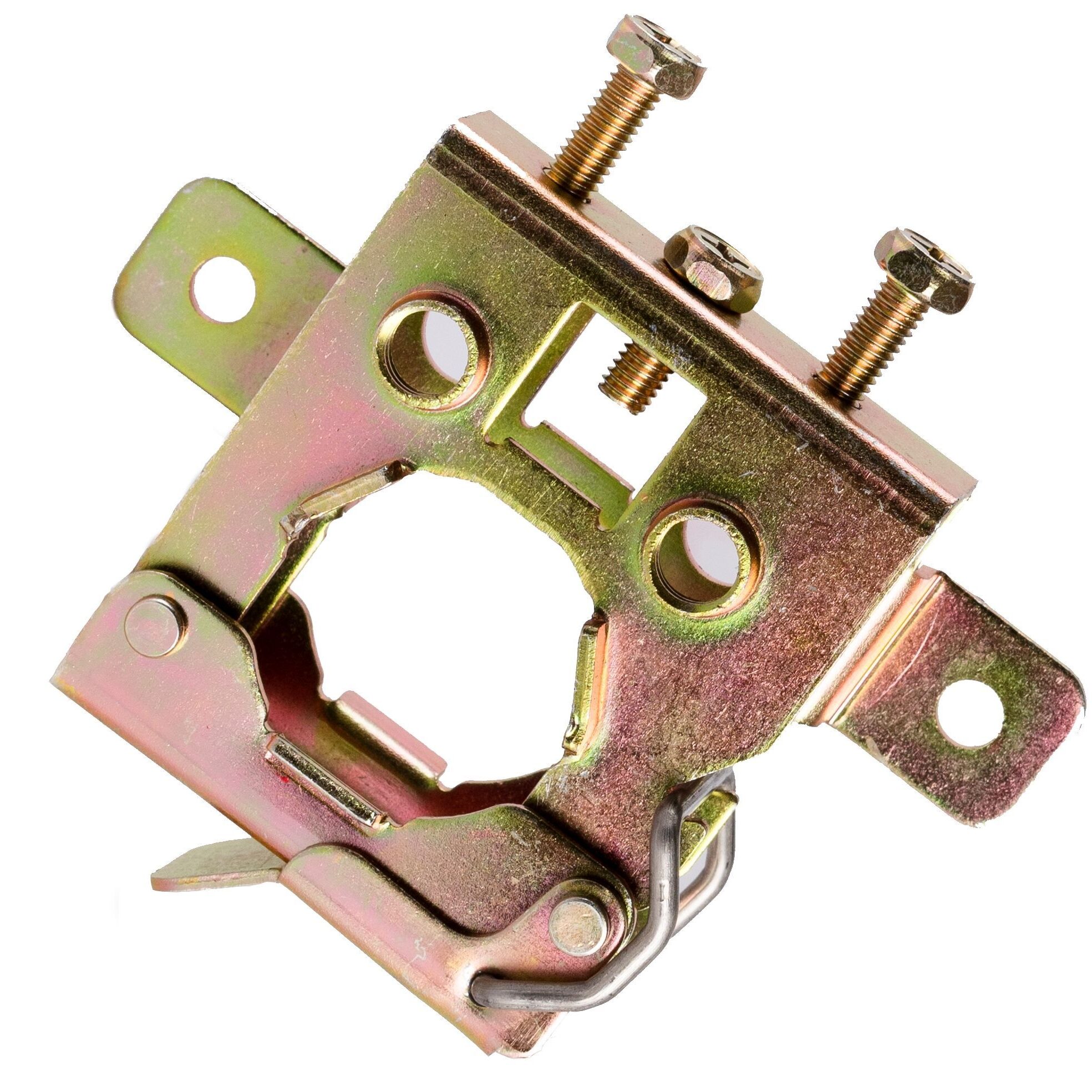
5. Center bracket
(GS-BOGH-MF)
Advantages
Fast installation
One of the outstanding advantages of the Specialty A1 is its extremely fast installation solution. Just one rod anchored to the concrete ceiling and one center bracket holds the sprinkler head to complete the installation.
Simple design
Instead of using 2 rods with a square bar and 2 side brackets, the Specialty A1 requires only a single middle bracket with one rod. With such a simple design, the construction of the flexible sprinkler hose is easier than ever.
Secure hand lock
Specialty A1's special center bracket alone has 3 different installation ways. With a hand-locking structure and a special clamping groove, the sprinkler head is fixed very firmly, there is no movement or looseness.
Technical Data
| Model No. | Rated working pressure (psi) | Max Ambient Temp (°F) | Nom Inlet by Outlet Size, (in.) | Hose assembly length (mm) | Number of bends | Minium bends radius (in.) | Equivalent Length of 1 in. Schedule 40 Steel Pipe (C = 120), ft |
| G-FLEX 25N-T700 | 200 | 225 | 1x1/2 | 700 | 2 | 4 | 33 |
| G-FLEX 25N-T1000 | 200 | 225 | 1x1/2 | 1000 | 3 | 4 | 57 |
| G-FLEX 25N-T1200 | 200 | 225 | 1x1/2 | 1200 | 3 | 4 | 68 |
| G-FLEX 25N-T1500 | 200 | 225 | 1x1/2 | 1500 | 3 | 4 | 82 |
| G-FLEX 25N-T1800 | 200 | 225 | 1x1/2 | 1800 | 3 | 4 | 98 |
| G-FLEX 25N-T700 | 200 | 225 | 1x3/4 | 700 | 2 | 4 | 38 |
| G-FLEX 25N-T1000 | 200 | 225 | 1x3/4 | 1000 | 3 | 4 | 62 |
| G-FLEX 25N-T1200 | 200 | 225 | 1x3/4 | 1200 | 3 | 4 | 73 |
| G-FLEX 25N-T1500 | 200 | 225 | 1x3/4 | 1500 | 3 | 4 | 89 |
| G-FLEX 25N-T1800 | 200 | 225 | 1x3/4 | 1800 | 3 | 4 | 104 |
Specification sheet according to UL standard
Model no. | Rated working pressure (psi) | Max Ambient Temp (°F) | Nom Inlet by Outlet Size, (in.) | Hose assembly length (mm) | Number of bends | Minimum bends radius (in.) | Equivalent Length of 1 in. Schedule 40 Steel Pipe (C = 120), ft |
G-FLEX 25B-T700 | 200 | 225 | 1x1/2 | 700 | 2 | 4 | 33 |
G-FLEX 25B-T1000 | 200 | 225 | 1x1/2 | 1000 | 3 | 4 | 57 |
G-FLEX 25B-T1200 | 200 | 225 | 1x1/2 | 1200 | 3 | 4 | 68 |
G-FLEX 25B-T1500 | 200 | 225 | 1 x 1/2 | 1500 | 3 | 4 | 82 |
G-FLEX 25B-T1800 | 200 | 225 | 1x1/2 | 1800 | 3 | 4 | 98 |
G-FLEX 25B-T700 | 200 | 225 | 1x3/4 | 700 | 2 | 4 | 38 |
G-FLEX 25B-T1000 | 200 | 225 | 1x3/4 | 1000 | 3 | 4 | 62 |
G-FLEX 25B-T1200 | 200 | 225 | 1x3/4 | 1200 | 3 | 4 | 73 |
G-FLEX 25B-T1500 | 200 | 225 | 1x3/4 | 1500 | 3 | 4 | 89 |
G-FLEX 25B-T1800 | 200 | 225 | 1x3/4 | 1800 | 3 | 4 | 104 |
Specification sheet according to FM standard
Model no. | NPT in. | K-Factor | Minimum bends radius (nn) | Number of bends | Rated working pressure psi (kPa) | Hose assembly length (mm) | Equivalent Length of 1 in. Schedule 40 Steel Pipe (C = 120), ft |
G-FLEX 25B-T700 | 1/2 | 5.6 | 230 | 1 | 175(1205) | 700 | 26(7.9) |
G-FLEX 25B-T1000 | 1/2 | 5.6 | 230 | 2 | 175(1205) | 1000 | 46.1(14) |
G-FLEX 25B-T1200 | 1/2 | 5.6 | 230 | 3 | 175(1205) | 1200 | 59.6(18.1) |
G-FLEX 25B-T1500 | 1/2 | 5.6 | 230 | 3 | 175(1205) | 1500 | 79.7(24.3) |
G-FLEX 25B-T1800 | 1/2 | 5.6 | 230 | 4 | 175(1205) | 1800 | 100(30.4) |
G-FLEX 25B-T700 | 3/4 | 8 | 230 | 1 | 175(1205) | 700 | 23.7(7.2) |
G-FLEX 25B-T1000 | 3/4 | 8 | 230 | 2 | 175(1205) | 1000 | 44.4(13.5) |
G-FLEX 25B-T1200 | 3/4 | 8 | 230 | 3 | 175(1205) | 1200 | 58.3(17.7) |
G-FLEX 25B-T1500 | 3/4 | 8 | 230 | 3 | 175(1205) | 1500 | 79(24) |
G-FLEX 25B-T1800 | 3/4 | 8 | 230 | 4 | 175(1205) | 1800 | 99.9(30.4) |
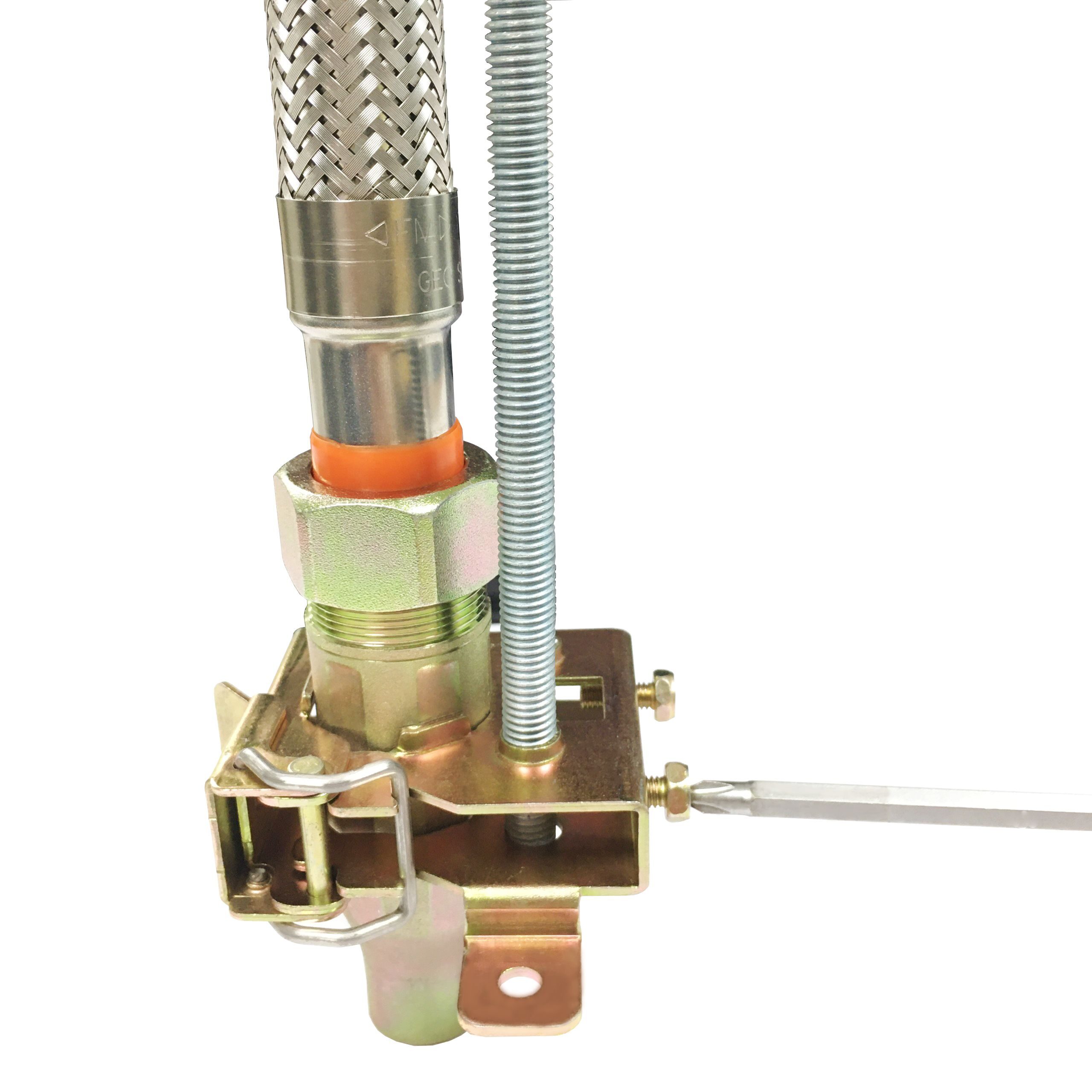
Specialty A1 Installation in laboratory
Specialty A1 can be used in various kinds of buildings